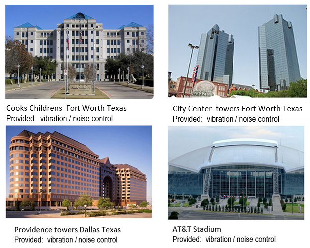
When first designing our newsletter, we had a decision to make. Did we want to focus on the New Premier Projects we were working on or did we want to go behind the scenes and highlight some of the projects we were called in on to provide solutions for vibration and/or noise problems.
We chose the latter, as this will be beneficial to our clients in two ways:
- To help clients who may have or had these experiences and not known who to call
- To make our broad base of our clientele aware of the expertise we have developed in fixing trouble jobs
This first article we have titled “The Call of Last Resort”.
The Call of Last Resort
It was the week before Thanksgiving and everything was great. We were preparing for the family holiday. Then we received a call stating that an inertia base we provided for a twin-cylinder, high-pressure, piston-driven, process air compressor located in a semiconductor plant, was allowing excessive movement and destroying braided stainless steel flexes in the attached piping.
Having been involved with large single-cylinder air compressors for decades, we knew when designing this base, we had to review the primary and secondary shaking forces. In checking our file, we had followed our procedure to the letter. Our calculations showed we needed a minimum mass of 1,156 lbs. The base we designed and installed had a mass of 3,000 lbs. — almost three times the mass required.
With this information in hand, we headed to a jobsite meeting and what a meeting it was. We met with the architect, mechanical engineer, mechanical contractor, chief facilities engineer, facilities engineers, steamfitters and Cornerstone Mechanical’s Terry Wilson. As the balancing contractor, 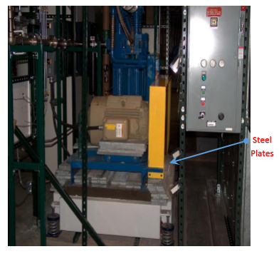 Cornerstone had the final responsibility of ensuring the equipment amplitudes were within allowances detailed in the project requirements. They were pretty much in charge of the show.
We received an overview of the situation and what attempts had been made to fix the issue prior to calling us. The initial amplitudes were at the motor, with peak amplitudes that exceeded 0.7 inch in the horizontal direction, 0.5 inch in the vertical and 0.4 inch in the axial. Seeking a solution, they first called the compressor manufacturer’s rep to inspect the installation. At the end of their inspection, the rep stated the compressor installation was installed correctly. So far, no solution to fix the problem. Cornerstone next tried adding 1,300 lbs. of more mass to our base by stacking 57 pieces of ¾” x 6” x 18” steel plates under and around the motor. (See photo above) While the effects were measurable, the amplitudes remained well above acceptable levels.
Their next step was to eliminate the effects of the spring isolators by inserting Unistrut at the four corners, between the bottom of the inertia base and the housekeeping pad. In effect, this shorted out the isolation, but further reduced the amplitudes to less than 0.3 inch at all measurement locations.
Next, Cornerstone tried using 2-inch thick rubber pads under the base, in the four corners. This increased the amplitude on the compressor to 0.4 inch. The arrangement that produced the lowest amplitudes was to support the compressor end of the base on springs and the motor end on rubber pads. This configuration produced peak amplitudes at the motor of 0.27 inch and 0 .29 inch on the compressor. It was at this point they made “The Call of Last Resort.” They called us.
We discussed our design criteria as described above and explained the inertia base should not be the problem. Well, when they turned on the compressor, the inertia base was dancing and the pipe was whipping. Having isolated similar equipment over the years, our gut told us the problem was not attributed to lack of inertia base mass, but rather to resonance of the compressor support steel.
We noticed the motor and compressor were supported by a structural steel angle base bolted to our inertia base. The steel support members under the motor and compressor were approximately 7 inches above our inertia base. When the compressor was in operation, this steel base support resonated excessively. This is what we believed to be the problem.
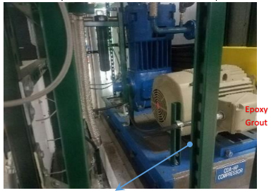 We recommended to fill the 7-inch void under the compressor and motor with Epoxy grout to eliminate the structural resonance and flexing. (See photo to the right). Then once the grout cured, readjust the spring mounts to the design spring deflection and the 2-inch operating clearance under the inertia base.
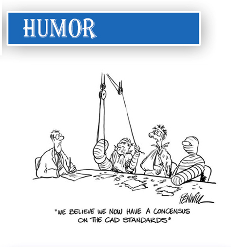
While not everyone in attendance agreed with our solution, they did agree to proceed with our recommendation since they had tried the previously noted solutions without success.
Well, now it’s the day before Thanksgiving and we were called to be present at the compressor startup. Talking about nervous — there were now some 30 people in attendance from senior management, Cornerstone, architects, engineers, etc. Since we were the guest of honor (and I use that phrase loosely), they placed us directly in front of the compressor and turned it on.
What a moment of anticipation – everyone wanting to head home to enjoy time with family and a date with a huge turkey and dressing. But none of that mattered if we had not provided a workable solution.
The compressor purred like the proverbial kitten and the amplitudes at the measured locations decreased to 0.15 inch, except for the axial which was 0.18 inch. All within the acceptable tolerances.
We chose this story as our very first because in all our years in this business (Phil Farco, Sr. alone has 50 years’ experience in the vibration and noise control field), we had not, nor have we since, seen a piece of operating equipment when initially installed, vibrate so violently that it destroyed a braided flex.
This is truly an example of Mason-Dallas to the Rescue! If you have a vibration or noise problem, we are only a phone call away at 817-267-8651. Make Mason-Dallas YOUR FIRST CALL!

Mason Stainless Steel Stock Hoses and Expansion Joints are safe for the New NSF-372 drinking water requirements
We were all excited by approval of the UL (Underwriters Lab) as manufacturers of NSF-61 low lead requirements for drinking water, but quickly dismayed to find NSF-61 was phasing out to an upgraded NSF-372. However, somebody up there loves us as we are the first company in the industry to be approved for the new NSF/ANSI-372 listing with the even lower lead limits for drinking water.
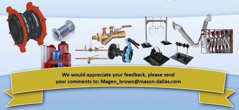
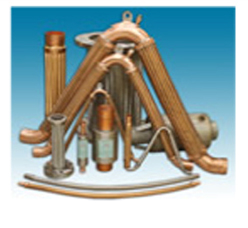
We have the widest variety of connectors and expansion joints covered by this approval in our industry. We stock a major supply of the MNSS (All Stainless Steel male threaded ends), VFLSS (All Stainless Steel Flanged End V’s), CPSB (All Bronze with Copper sweat ends), VCPSB (All Bronze V’s), and ECCPS (Bronze and Stainless Steel Expansion Compensators).
This NEW NSF/ANSI-372 listing applies to virtually every size and length of the all BRONZE and STAINLESS STEEL braided metal assemblies which includes the V-Loops and the straight assemblies, as well as many
non-standard assemblies. Also included in this approval are Stainless Steel and Copper Expansion Joints.
A complete list of the NEW NSF/ANSI-372 items and submittals can be seen on our website, www.mason-ind.com.
Contact Mason-Dallas, Inc. at 817-267-8651 for pricing.
Mark Laboe – Product Manager